The end of the Pelco era
 In 2013/2014 I was part of a research effort at Pelco that identified the drivers of new surveillance technology. We wrote two different white papers during that time, with me as the author and editor.
The research lead, Sam Grigorian, demonstrated the importance of asynchronous cores in video processing. Co-researcher Fida Almasri identified the necessity of accelerating Pelco’s production cycle in order to stay competitive, and I argued that cell phone processors could allow us to leapfrog new surveillance systems and be our new platform for advanced surveillance hardware.
Our white papers explained that we are at a very interesting and challenging place in Moore’s Law.
In tech forums I often see people write about the end of Moore’s Law as if it meant the end of innovation. I often read people who claim that the limit of miniaturization is coming “soon”.
The truth is that Moore’s law is slowing down. Processing cores have just barely made it to the 7 nm node of semiconductor device fabrication. 5 nm semiconductors have been constructed and demonstrated in the lab. We may see these in commercial production around 2020.
The Lawrence Berkeley National Lab demonstrated last year that it is possible to create a transistor with a working 1-nanometer gate.
If researchers solve the problems of quantum tunneling and of removing heat from processor cores then we could see miniaturization of up to 3 to 1 nm before we hit that final wall of physics in this technology.
And then we will need to advance in other technological directions to allow for the increase of switching devices per volume.
However, the end of shrinking transistors doesn’t mean the end of innovation.
Quite the opposite. As we pointed out in our white paper, technological innovation is accelerating. It is being driven primarily by cheap and easy to use processing cores. The rate of innovative change has accelerated to a point where is is difficult or impossible to predict new technology further than 18-months out. And the rate of technological innovation seems to be increasing.
It has become much easier to solve advanced technological problems by throwing a handful of transistor dense processor cores at it. But this leads to a different problem. Multiple processors work best with parallel processing. And our technology is still in the infancy of parallel programming.
Development environments for parallel programming are sorely lacking. Parallel programming environments are not easy or intuitive for human programmers. We are still coming to terms with the problems identified by Amdahl’s law – a formula used to describe parallel computing workload and used to indicate the hard limits on how many parallel processors may be used to solve a given processing task.
Even the latest and best Integrated Development Environments designed for parallel design require software “tweaking” and other kludges by the software engineer. As the development environment matures we should see even more gains in innovation.
Back to Pelco
 These were the challenges for Pelco in 2013. Accelerated innovation necessitated a decreased production cycle. Advanced surveillance systems required embracing asynchronous processing cores. And video over IP was transitioning to advanced networks using better hardware and compression methods.
Pelco once dominated the security marketplace using advanced technology in a market that was traditionally low-tech. So it is somewhat ironic that Pelco couldn’t or wouldn’t keep up with technological advancement in the security industry.
Faced with the urgency to dramatically upgrade their technology and production processes to keep up in this accelerating environment of innovation – they blinked.
And Pelco’s parent company at that point decided to let Pelco’s era come to an end.
At one time Pelco employed over 2,000 people. There are under 1,000 people at Pelco now. Another 200 will be laid off from Pelco during 2017. And I’ve been told that the Clovis manufacturing facilities will be closed at the end of 2017. Any employees not working for Schneider Electric – Pelco’s owner – face an uncertain future. There are still a few product lines that are or will be transferred to other facilities.
The white papers that I helped create may have been one of the last straws in this decision.
Makers, you can develop an embedded system like an engineer.
Semiconductor manufacturers will often showcase their microcontrollers in an engineering evaluation board. These boards are loaded with features and peripherals that are useful in various ways, and because of this they are often relatively expensive. They are usually out of the reach of the Maker community, and even some of the smaller design houses may avoid them due to cost.
 But the Maker Community has become home to several low cost microcontroller boards that could be used in an engineering development environment. At the very least, it will allow hardware engineers, or even hardware technicians, to set up a low cost minimum platform that can be turned over to microchip firmware programmers for initial development and testing.
Even better, these boards can be coupled with low cost engineering-level hardware and software to provide a learning platform for those Makers who are interested in breaking into embedded systems programming.
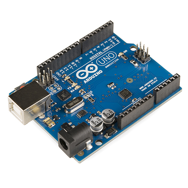
The main two boards used by the Maker community are the Arduino and the Arduino-compatible Microchip / Digilent chipKIT. These two boards are designed to be easy to program using the standard Arduino Integrated Development Environment (IDE). But there is nothing that requires the Arduino IDE. Instead, relatively inexpensive engineering-level microcontroller design tools can be applied to these Maker boards.
Almost 15 years ago I designed a product around the Hitachi SuperH SH-2 microcontroller. It was a wonderful device and very powerful for its time. It was the engine that drove the Sega Saturn game console. These microcontrollers required the use of an In-Circuit Emulator (ICE) and a bond-out processor that cost tens of thousands of dollars. The ICE emulated every part of the microcontroller, and was popped into the prototype PCB for the software developer. The ICE allowed the programmer to see quite a lot of what was happening inside the SuperH microcontroller – including individual registers in near real-time. Once the firmware was developed and troubleshot, it was packaged and sent to a parts distributor, who programmed the SH-2s for us before our production line added them to the circuit board. Firmware changes were made with the ICE, and added to our Production pipeline through change orders.
Today, in-circuit emulation has been mostly replaced by on-chip debugging hardware. The Joint Test Action Group industry association implemented standards for on-chip testing using a dedicated debug port on microcontrollers. These debug test access ports are used with a protocol that gives the engineer access to the device logic levels and registers.
Different manufacturers implement JTAG somewhat differently, and many manufacturers (Microchip, for example) have their own device serial debugging ports. This has led to the use of JTAG programmers for programming the printed circuit board in an Automated Test Equipment environment, and to manufacturer specific In-Circuit Debuggers (ICD) used for developing an embedded system.
ICE is expensive, and with newer microcontrollers it is unnecessary. JTAG programmers are useful, but not as useful as an ICD. And In-Circuit Debuggers have become cheap enough for the Maker Community to purchase.
ATMEL makes the AVR microcontroller that is used on the Arduino. And while a Maker could use the Arduino IDE to create something new, there is really nothing stopping anyone from using the ATMEL engineering design system. The ATMEL IDE, Atmel Studio 7, can be downloaded for free. ATMEL recommends several different ICDs, from low-cost to professional level. The mid-range and low cost ICDs are under $60. The professional level ATMEL development ICD is about $660. All are useful for product development. The difference between the debuggers is mostly in the speed at which the ICD can communicate with the PC, which affects programming speed and the number and speed at which registers are displayed in the IDE.
 Microchip (who recently purchased ATMEL) also has an IDE that you can download, called MPLAB. The most current version as of this writing is MPLAB X, and there is a version of MPLAB that can be used on the Cloud. Microchip has a lot of 3rd party ICDs and even more simple serial device programmers. It is quite possible to purchase an ICD for under $40 for the Microchip PIC microcontrollers. The Microchip “official” ICD is the ICD 3, a USB-connected ICD that is widely used for developing embedded systems. You can purchase the ICD 3 for about $280, including shipping, from Microchip Direct.
So a member of the Maker community could purchase an Arduino Uno, download the Arduino Software IDE, and start programming almost immediately.
OR, a Maker could get an Arduino Uno, download Atmel Studio 7, check out the ATMEGA 328P datasheet (PDF), purchase one of the recommended ICDs, and then learn how to interface it with the Arduino’s microcontroller. A Maker could do the same thing with Microchip’s chipKIT using MPLAB and a PIC compatible ICD – or the Microchip ICD-3.
No, this won’t be as simple as the Arduino environment normally used by Makers, but this is a good start for learning how to really design an embedded system. This is an excellent opportunity for anyone interested in learning the basics of embedded systems design and programming.
And finally, Arduino and chipKIT are not the only players on the market. There are others that are compatible, or not compatible with the Arduino IDE. And each manufacturer has either its own IDE, or is compatible with an open source IDE.
Smart Aquaponics – defining the new system
So in my last post, I started describing the basics of controlling the flow of water in a complex aquaponics system. Here are some other constraints that I will be adding to my design.
- The design must get the best “bang” for the buck.
For the most part, I’m going to try to use inexpensive materials that are easy for me to acquire locally. For example, I don’t mind putting extra effort into cleaning up used IBCs if doing so saves a lot of money. As always, I’ll try to gauge my time against the cost of the item.
- The design must be power efficient
To accomplish this, I’ll be using a very efficient water pump that is always on. I am planning on using only one, high rate of flow pump. While it is possible to use several smaller pumps to more easily move the water around the system, this isn’t very efficient, and could lead to multiple points of failure. It is also possible to cycle the power on a pump to increase power efficiency, but in doing so the lifespan of the pump suffers. More reliable pumps and “soft start” pump controllers are more expensive. There may come a time when I rethink cycling the power on pumps, but first I’ll design a system that doesn’t require this.
- Shorter amounts of PVC pipe
The water will come into my system through city water, and it will either leave my aquaponics system through the city sewer, or be diverted to my lawn, flower beds and garden. I would prefer any water leaving the system go to my lawn or garden, but there may be times that I will want the used water to go directly to the city sewage treatment. I see this as several different PVC systems that include, 1) water delivery from the city to the system. 2) Water flushed from the system to the city sewer or to storage for lawn / garden. 3) Water delivered from the sump to the grow beds and to the fish tanks. 4) Water returning from the grow beds and fish tank to the sump.
I may make use of bridge siphons to connect parts of the system, and I will use flow restrictors for things like hanging towers of strawberries.
- Parts are easy to repair or replace
This means that anyplace I add a valve, pump, or other PVC connection, it should be installed in a manner that is easy to disconnect and replace with a new part. Valves should be easily repaired with standard tools.
- System must “fail safe”
If power goes out or the pump fails then the system should not flood at any point. Grow beds should drain completely, and fish tanks should stay full. If any valve fails in the open, or closed, position then the system must alarm, and the system must not lose water. There should be hooks built in for monitoring water levels and flow rate.
- System is easy to expand
If I want to add grow beds, fish tanks or sump tanks, it should only be a matter of space and a little extra plumbing.
- System is easy to clean
Solid waste should usually fall to an easily collected place. A standard pond vacuum cleaner should be able to reach all parts of the fish tanks. Grow beds should be easy to clean. This isn’t about bio filtration of waste – not yet.
Constraints are key to system design
I’ve read that any problem is easy to solve if there are no constraints to worry about. Sending a man to the Moon is relatively cheap and easy if you’re not worried about food, water, air, or an eventual return to Earth. It is constraints like this that define the challenge. And stating them clearly is a good way to start.
What must be understood is that at the start of a project, we really do not know what all the constraints might be. So I’ll be prepared to update this list.
Smart Aquaponics Control System – An Internet of Things project
In my last post, I’ve said that I want a project that helps me control an aquaponics system. These are both very vague goals, and I need to narrow them down, and then I need to figure out how to do them. It seems a bit silly to use Project Management Processes and Product-Oriented Processes to define and control my project when I am simultaneously the management, employee, and customer. However, it is still useful for me to define the project in these terms in order to create a timeline, benchmarks, and goal.
To start this I’ll first define what sort of aquaponics system I want to control, and speak about the constraints I must follow. As an aside, I’ve heard it said in many different contexts that any problem is easily solved if you do not have to worry about constraints. Even sending humans to Mars becomes much easier if you don’t have to worry about them arriving alive – or ever departing again! A round trip to Mars with living humans is considered a “constraint”.
What is an aquaponics system?
Aquaculture is the raising of fish (or other aquatic animals) for food. Such a system requires food and clean water, and the wastes from the system must be filtered out of it and disposed of, or else the system will become deadly to its animals. Hydroponics is the growing of plants in water for food. This sort of system requires that the water be fertilized and filtered, and watched for build-ups of waste and metals, or else the plants will die.
Aquaponics is a combination of these two methods of growing food, such that the wastes of the aquatic animals are used as fertilizer for the plants, and the plants clean the water for the animals. There is also a layer of nitrification bacteria in the system that break down ammonia and nitrates into nutrients for the plants.
 In a perfect aquaponics system, you put fish food into the system, and you get meat and plants out of the system. Having said that, no aquaponics system is perfect, and a certain amount of tweaking the system is necessary.
To the right is a good example of a very simple aquaponics system. This system uses a pump to move water from the fish tank to a filter tank. The filter tank is filled with media that houses nitrification bacteria. This describes nothing more than a standard aquarium, and such a setup can be very stable, needing little in the way of maintenance if the ratio of fish to bacteria stays stable, and if distilled water is added to the system to compensate for evaporation losses.
The addition of plants to such a system runs into an immediate problem. Some plants cannot survive with having their roots constantly submerged in water. They need to be able to have access to air. One way of doing this is to periodically drain the upper media tank several times a day. A good mechanical way of doing this is to use a self-starting siphon called a “Bell Siphon“.
In short, a Bell Siphon will start to siphon water from the upper tank when the water reaches a certain depth. It will stop pulling water out of the upper tank when the water level drops below the rim of the Bell dome, which is typically near the bottom of the container. If the container is sloped toward the siphon, then most of the container will be completely drained.

This simple siphon works fine for a small aquaponics system. Something like the one shown to the right. This is a 150 gallon tank with an 80 gallon media bed. At the time of this photo, I was experimenting with Bell siphons, and had not added media to this project.
But what happens when you have multiple fish tanks? What happens when you have multiple media beds for your plants? What do you do when you want to add other aquatic animals besides just fish? Like freshwater prawns or mussels?
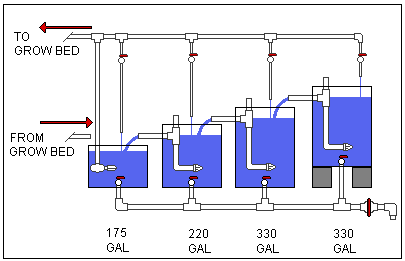
As I continued to play with aquaponics systems, the next thing I knew I had over a thousand gallons of fish tanks, and I was trying to find ways to circulate their water, and also to be able to drain them when I needed to clean them. This is what I came up with.
This system doesn’t even count the plant grow beds. It also uses a common sump tank as a shortcut. It did have the advantage of allowing me to drain a tank if I needed to do so, but with the disadvantage of requiring me to re-route the circulation if I wanted to cut off a center tank.
I actually built this system, and documented it on my permaculture website, with a video of it in action. You can see this here.
And I ran into a problem. Okay, one of the problems I had is that I had to move, and was required to disassemble the system.
But what I consider to be the bigger problem is how the system worked together. If I added grow beds to the system, I had to be concerned with my sump “bottoming out”.
The grow beds that I want to use are two feet wide, four feet long, and 14 inches deep, with 12 inches of media. This translates into 60 gallons of media and water together, or about 25 gallons of water per grow bed. This means I can have no more than 7 grow beds before my sump goes bone dry. Or less than 6 grow beds if I want to keep my sump pump underwater.
This also doesn’t account for water diverted to strawberry towers, lost in evaporation, or used in other ways. I would like the ability to use 10 grow beds or more, and use the sump itself (with a screen around the pump) for growing catfish. So a certain amount of water must remain in it.
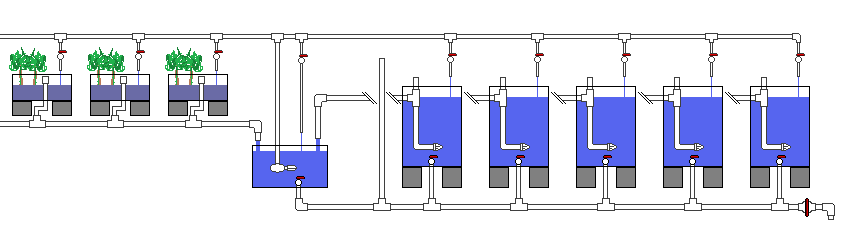
This is what I came up with… multiple tanks, multiple grow beds. Of course, the sump would have to be larger, just in case all the Bell siphons achieved synchronicity and allowed all the grow beds to fill up at once. There would have to be enough water for everything.
Each of those red handles represents a valve that can be turned off or on by hand, and that I would be expected to fiddle with to get the right rate of flow for the system. And while this is quite acceptable with a smaller system, it becomes a problem larger systems.
Luckily valves and pumps can be controlled through electronics. I wanted an inexpensive method that I could create, and that I could offer to the Maker and Aquaponics community. I’ll talk about that next as I more formally describe the scope of this project.
The Internet of Things – a new project
It’s been a week since I attended the UBM West conference in Anaheim, and I’ve acquired a new fascination with the Internet of Things. In fact, I’ve been more than a little fixated on it since coming home.
I have been having discussions with various friends in engineering about the IoT, and I can see that there is a lot of potential here, but also there is a lot of confusion, and companies working at cross purposes. The consumer marketplace is quickly adopting many different IoT ideas, while manufacturing seems to be talking a great game, but is adopting the Industrial Internet of Things (IIoT) slowly – if at all.
One of my software friends is pushing the Internet of Data – the idea that the device doesn’t matter, only the data. As part of the setup, the device explains to the network what it is, what it can do, and what data it can provide. It is up to the network to determine how to use this information.
Unfortunately, there is not industry standard for data sharing in the IoT. There is no real standardized Human/Machine Interface (HMI) to allow a human to interact with a local network of IoT to do useful things. The IFTTT web service is a useful idea of how such an HMI might work, but I’m having a hard time visualizing how it would work in a local network setting – where I could control the devices in my home through my tablet computer, or where a manufacturer could use it to choreograph several manufacturing robots to work together.
I’ve learned that there is a lot of pre-existing infrastructure and technologies for IoT, and there are several services that hook into it. The problem is getting them all to work smoothly together.
But reading about it all is completely different from actually doing it. And to learn, it is often best to create a project to accomplish something, and then learn from that.
So I’m starting a project.
If you know anything about me, you may know that I’m interested in permaculture. Permaculture is the creation of sustainable agricultural systems by studying and simulating the ecological systems found in nature. It is the idea of working with nature, fitting our society together with ecology. There are principles of design that guide permaculture, and they are useful – but they all boil down to a simple idea, human observation and reaction as a form of feedback is key to an agricultural system.
I’ve been writing about urban farming and aquaponics in my blog, “Fresno Backyard Harvest” for a few years now. Aquaponics has been of great interest to me as part of urban farming and permaculture. And I would like to better automate my urban farm, with controls that monitor plant moisture, measure water quality for my fish, and adjust water levels when necessary. I’d also like alarms when something goes wrong, and I would like to see how much of my urban farm I can measure.
For my first project, I intend to create something that will control a small aquaponics setup. I will use it to monitor various sensors, and report back to me. It should also control water flow.
Right now, I’m in the planning stage. I’ll keep a running journal of how I decide what to use, and what my designs look like. I’ll also keep a Github repository of each project.
You’ll be able to find my progress in the “Projects” category of my blog. Starting with this one. As my projects split off, they’ll be given their own categories.
Industrial Internet of Things, Disruptive Manufacturing at UBM West Exibition & Conference
 I’ve enjoyed engineering journals like EDN, EE Times and embedded.com for years. So when I found out that the UBM “mothership” was hosting a conference in Anaheim, I was eager to attend.
I haven’t always had the freedom to attend any conference or exposition that I wanted. Employers are understandably reluctant to send engineers to expensive conferences. But these events “feed” the engineer with new ideas. They let us know what is possible. And of course they allow us to network and connect.
I would recommend to any engineer that he or she attend at least one or two conventions every year. If your employer will not send you, then plan on taking some vacation time and pay your own way. The benefits are too great.
I spent two days here and according to my pedometer I walked 14 miles through the aisles. Besides aching feet, here’s one of the biggest things that I’ve taken from this event.
 The Internet of Things has become the Industrial Internet of Things. Manufacturers have embraced IoT to connect and control their production lines. But it seems to me that the manufacturing model still relies on the Ford assembly-line model and the power that comes with IIoT is underused.
I think that part of this is due to manufacturing inertia. And this is understandable, if the company is still making a profit then why change? This inertia is coming to an end due to narrowing profit margins that are required for manufacturers to remain competitive. We seem to be seeing changes due to this already.
I also think that the Maker community is becoming more powerful and is approaching the point where the community itself will become a “disruptive technology” for traditional manufacturers. Makers have moved beyond “arts and crafts” and are connecting with smaller designers and specialized manufacturers to create small runs of innovative technology products. This distributed manufacturing model is coordinated “in the cloud” and is capable of creating printed circuit boards at a cost of tens of dollars per square inch for limited runs.
As distributed manufacturers start to coordinate with each other I foresee a time when they will create virtual vertical integration, and the manufacturers themselves will be mapped into resilient supply chains. Information technology will be used to control individual machines, reconfigure production lines, and select supply chains based upon availability and costs. Manufacturing will just be another part of that supply chain, easily and quickly replaced by another manufacturer in the case of failure.
This has been called “Industry 4.0”, which was also discussed at UBM Anaheim. And one of the six design principles of Industry 4.0 is “Interoperability”. And this seems to be another sticking point in manufacturing. As of right now, there is no standard for the Internet of Things. Or rather – there are several standards that don’t play well together. And since these smart factories depend on IoT, it is imperative that these things can talk to the rest of the virtual factory.
Customer design goes in, product comes out. We’ve got a long way to go – but I think that time is measured in years, not decades. Our consumer products will someday follow the “on demand printing” model in that the product will reside in a catalog until ordered and produced.
Understanding the Challenge of Communicating Underwater: Underwater Acoustic Networks

In 2004 the National Oceanic and Atmospheric Administration returned to explore the remains of the RMS Titanic. They used Hercules and Argus, two remotely operated vehicles that were connected to the scientific ship by an expensive communications tether long enough to reach 2.4 miles to the sunken ship. No other communication methods exist that can give scientists the real-time video required to pilot the ROVs.
Fast communication technologies are relatively common. Modern WIFI routers allow muli-gigabit connection rates, with IEEE 802.11ac offering transfer rates of up to 6.77 Gbit/s, depending on hardware.
But communicating underwater is difficult. Water highly attenuates radio frequency (RF) signals, limiting these signals to very short distances or very low transmission speeds. Optical based communications are also limited due to high attenuation of the signal, node alignment problems, and signal obstruction by marine objects and turbidity.

Simple long-distance underwater communication has always been available. Since the dawn of sailing humans have heard mysterious underwater sounds that have turned out to be marine animals communicating with each other over long distances.
The underwater acoustic wave guide called the Deep Sound Channel (DSC) was discovered by Russian and American scientists. Sounds made at the depth of the DSC travel great distances. This was used during World War II in the creation of a long-range position fixing system called a “SOFAR bomb”, used by ships or downed pilots to secretly report their location.
Modern acoustic communications tries to take advantage of several properties of water – especially deep water. But it is restricted to very slow connection rates. It is also vulnerable to signal path reflections, Doppler spread, longer signal travel times, and quickly changing rates of signal attenuation due to water chemistry and depth. Under excellent conditions with very short signal paths, acoustic connect rates of up to 150 kbit/s are possible, but reliable connect rates of 40 kbit/s are more realistic.
An example of modern acoustic modems is the S2CM series by Evo Logics. One modem in this series has a connection rate of about 60 kbit/s with a range of 300 meters and a depth of 200 meters.
One of the bigger challenges of underwater acoustic communication is a quickly changing physical environment – especially if at least one transceiver node is in motion. Constantly changing underwater terrain, depth and water composition make it difficult for Underwater Acoustic Networks (UAN) to keep up. Lack of standardization between manufacturers also creates interoperability issues between different underwater acoustic modems.
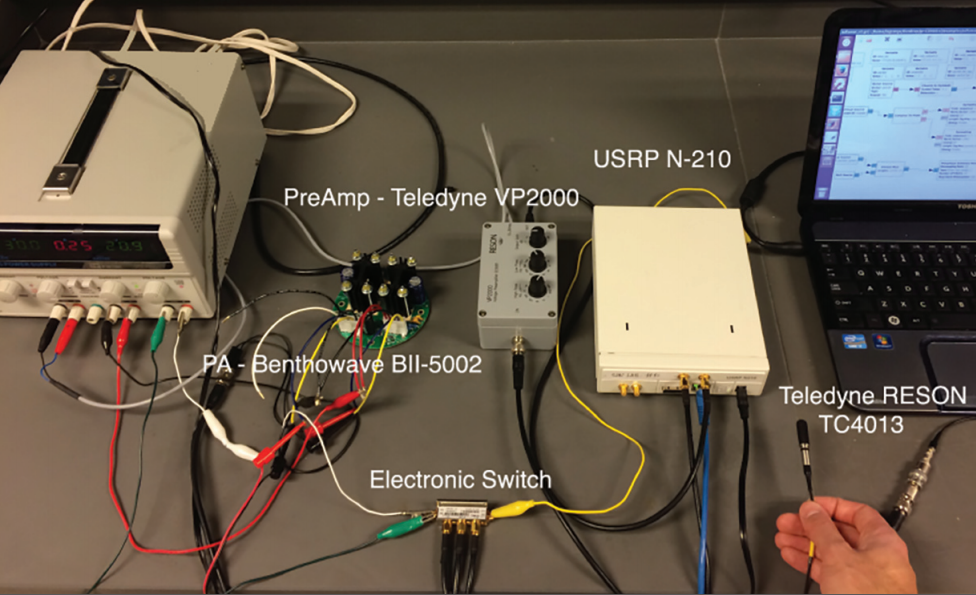
IEEE Communications Magazine recently published a paper [1] detailing the use of software defined radio as a way of coping with the challenges of experimenting in an uncertain physical environment. According to the paper, University of Buffalo engineers are attempting to adapt Software Defined Radio (SDR) principles to underwater acoustic modems in the proposition of creating a Software Defined Acoustic Modem (SDAM) that can be easily reconfigured to allow better testing capabilities of various hardware and software underwater acoustic networks.
The Buffalo engineering team combined commercial off-the-shelf components and open source GNU Radio SDR software to create a highly configurable prototype SDAM that is half the cost of less agile commercially available alternatives. The SDAM prototype supports IPv4 and IPv6 Internet communications protocols.
Experiments were created by the engineering team to demonstrate the real-time adaptation capabilities of the SDAM prototype in a real-world environment and in the lab. Namely in a shallow lake, and in water tanks. Interference signals were used during these experiments and the signal-to-interference-plus-noise ratio (SINR) was measured and compared to clear channel transmissions. The adaptive transmission methods that were tested were shown to reduce the bit error rate during the transmission, as compared to more standard fixed transmission rates.
While this paper did not demonstrate a dramatic improvement of underwater data transmission speeds, it did demonstrate a way of creating a Software Defined Acoustic Modem that is less expensive and vastly more configurable than commercial models. This prototype is an excellent jumping-off platform for the further development of inexpensive SDAM based communications, which should allow other engineers to experiment with other adaptive underwater transmissions, and even with multi-path networks.
And this is where this paper becomes important. Software defined radio has caught fire in the engineering and hobbyist community, and is making great strides because of this. By piggybacking off of SDR, SDAM is making experimental underwater acoustic communication available to a wide audience.
[1] Demirors, E.; Sklivanitis, G.; Melodia, T.; Batalama, S.N.; Pados, D.A., “Software-defined underwater acoustic networks: toward a high-rate real-time reconfigurable modem,” in Communications Magazine, IEEE , vol.53, no.11, pp.64-71, November 2015
doi: 10.1109/MCOM.2015.7321973
URL: http://ieeexplore.ieee.org/stamp/stamp.jsp?tp=&arnumber=7321973&isnumber=7321957
Where online security fails – Social engineering and Amazon
![]() Customers concerned about security try to do all the right things. They use randomly generated unique passwords for every online service, and keep those in a keylogger. They use 2-step verification. They look for HTTPS secure connections. And yet a little social engineering is all it takes to undo this hard work.
Customers concerned about security try to do all the right things. They use randomly generated unique passwords for every online service, and keep those in a keylogger. They use 2-step verification. They look for HTTPS secure connections. And yet a little social engineering is all it takes to undo this hard work.
The Internet retailer Amazon has just demonstrated how devastatingly effective social engineering can be applied to its users.
Yesterday, Eric Springer, a writer on the Medium blogging community described how his Amazon account was breached by someone who impersonated Eric over Amazon’s text-chat service. The impersonator knew Eric Springer’s name, and email address. Both of which are easily found online for almost everyone who uses the Internet.
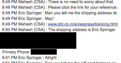 The impersonator did not know Eric’s real shipping address, and instead used the address of a hotel from the same zip code. He found the zip code by investigating Eric’s website registration information. The impersonator got this information from a simple WHOIS inquiry.
You can see from Eric’s description that the scammer was able to use this fake address to get Amazon to give him Eric’s real shipping address and phone number. From this the scammer was able to get Eric’s bank to issue a new copy of Eric’s credit card.
It didn’t matter how complex Eric made his password. It didn’t matter that Eric was using two factor verification. A guy was able to breech his security using chat, and later by merely calling Amazon and speaking to them.
Frankly, the scammer did too much work. It is amazing how much information can be found about most individuals by merely googling their names and city online. For those people who live in bigger cities, googling their name and zip code is usually sufficient. Unless the target has a name as comfortably anonymous as “John Smith”, they usually easily found.
Companies will usually follow up a communication with an email, or even regular postal mail. This isn’t enough. Email has become flooded – if you use email you must aggressively monitor and filter it to be useful. Scammers count on the fact that most people do not watch their incoming email too closely. Email services may automatically filter messages by importance, and the email that you reply to is often on the top of that list. An email conversation with a best friend or employer ranks much higher than an unanswered notification from a financial service.
Here are some things that may help you.
- First, use a credit card service that texts your phone whenever anything is charged to your credit card. Capital One offers this service with a “threshold” charge you can set before you are notified. Casual credit card users will find this useful.
- Next, every month go over your charges, and follow up any charge you do not recognize. Notify your financial institution for any fraudulent charges.
- Create and use “Business only” email addresses. Google’s Gmail address alias format allows you to use your normal email address (Jdoe@gmail.com) as a special purpose address (Jdoe+BofA@gmail.com). This is done in a “your.username+any.alias@gmail.com” format.
- Set up two-factor identification on any service that has access to your financial or personal information.
- Use a password manager that can randomly generate, store and use strong passwords.
And last, demand that your service conforms to good safety practices. Eric’s response from Amazon was less than stellar so he published his results with the Reddit social networking community. Afterwards many other users repeated Eric’s experience by successfully social engineering their own accounts. After about 8 hours, Amazon changed their procedure and started demanding better security checks and stopped allowing successful social engineering. But it took public social shaming to get this result from Amazon, which is really disappointing.
Professional development
I’m currently working on several areas of professional development.
- FE Exam – I’m working toward my Professional Engineer license for Electrical and Computer engineering. My first step is to take the Fundamentals of Engineering (FE) Exam. I plan on taking the FE Exam this fall.
- CAPM Certification – I’m studying for the Certified Associate in Project Management certification. I will apply for the CAPM certification in June / July.
- Software / Firmware – I want to keep up my skills in firmware programming, so I’ll be developing an embedded project in C++, and an Android platform project in JAVA.
Other things I’m working on include:
Programmable Logic Controllers – I’m really interested in using PLCs for my own permaculture / aquaponics projects. I’ve downloaded the PSIM PLC simulator, and am looking at purchasing a copy of PLCLogix when I’m have a better handle on the different languages.
I’ve also ordered a chipKIT uC32 based on the Microchip PIC32MX340F512H. I’ll use MPLAB X and a Microchip ICD to program it. My idea is to eventually use this to measure water levels and quality in an Aquaponics setup. I’ll be programming it in C++.
And finally, it’s time to upgrade my Amateur Radio licence class again. I’m currently a General class ham (KD6TXV) and want to upgrade to Amateur Extra class. I’ll be taking the exam this summer.
Microchip purchased Atmel – Some background and what this could mean to the Maker community
 Traditionally if engineers needed a small microcontroller that was easy to use and program, they would likely choose a Microchip PIC. A design was still required to couple the microcontroller together with a power supply, clock, and I/O, but that was relatively simple for any engineer. The software was a little more difficult since the PIC was programmed using Microchip RISC assembly language.
This was less useful to the Maker community, who could understandably find hardware design and the Microchip PIC environment to be very confusing.
Then in 1992 the Basic Stamp 1 by Parallax came along. This device used a Microchip PIC on a small circuit board with its own clock, I/O, and power supply. It also had FLASH memory. The PIC ran an interpreter program, and the user could program it in a version of Basic (PBASIC). The most important aspect of the Basic Stamp is that it allowed the fledgling Maker community to create real microcontroller-based projects. But the Basic Stamp has always been too expensive for Makers.
In 2005 the Arduino was invented as a lower cost alternative to the Basic Stamp. Based on open-source hardware Arduino boards could be manufactured by anyone. It was originally designed to use the ATMEL AVR microcontrollers, and this tradition has continued on from 8-bit to 16 and 32 bit AVRs. Manufacturers have created Arduinos based on different microcontrollers too, which isn’t a problem as long as the board is compatible with the Arduino IDE and libraries.
Arduino boards have a wide range of abilities and features and can be programmed in multiple languages. A simple Arduino board can be purchased for under $20. These features make the Arduino a very handy device for the Maker community.
Microchip is still the 800-pound Gorilla in the microcontroller and memory marketplace. And this marketplace has been consolidating as margins grow tighter. Microchip just purchased Atmel for $3.6 billion.
What does this mean for the Maker community?
Microchip has always tried to be attractive to the Maker community. Its parts are very inexpensive, and it provides explicit guides of “how to” build a complete circuit board based around its PIC microcontrollers. For a while the Maker community seemed to be moving toward Microchip, with books like “Easy PIC’n” becoming somewhat popular. Microchip had a market share in the Maker community as long as they were competing with the Basic Stamp and its expensive counterparts. That seemed to fall away when the Arduino arrived.
Microchip, along with Digilent and Fubar Labs, decided to create their own open source hardware platform to compete with the Arduino and Raspberry PI. Billed as “Arduinos on Steroids” this platform is called the chipKIT, and it uses the very powerful PIC32 series of microcontrollers as its engine. The chipKIT boards were introduced in 2013 at $20 for the low-end boards. These boards were supposed to be able to port code created for the Arduino right into the chipKIT.
However, increased raw power and a different microcontroller have created problems with library compatibility. This isn’t a big problem for programmers who are used to tweaking libraries for their own use, but the Maker community values greater compatibility and ease of use, and many do not have a need for the power available in the chipKIT. The chipKIT has a decent market niche, but the Maker community really loves Arduino.
Now that Microchip owns chipKIT and Arduino, it will be interesting to see if a pathway is created to urge Makers on to more powerful products. A partial pathway already exists since chipKIT can be programmed with either the Arduino IDE or with MPLAB and its In-Circuit Debugger.
Microchip shines with excellent product support and online designer forums. But these tend to cater to engineers more than Makers. ChipKIT questions do not get the immediate response that other PIC questions elicit. Some engineers on the Microchip forums have a dismissive attitude toward the Maker community too.
It would be to Microchip’s advantage to create a Maker community forum as part of their otherwise excellent forums, with Maker-friendly moderators and assistance. They could combine this community with the Arduino and the chipKIT Makers. Maybe Makers can be encouraged to join the engineering career fields.
From a personal note – I’ve always loved the Microchip PIC, and have programmed it in RISC and C++. I’ve also programmed the Arduino in C++. If Microchip can make the libraries easier to use, the PIC32 has some serious power I’d love to play with in an Arduino environment.